Comtech EF Data CDM-840 Specifications Page 29
- Page / 244
- Table of contents
- BOOKMARKS
- MN-CDM840 Revision 2 1
- Errata A for MN-CDM840 Rev 2 3
- CDM-840 5
- TABLE OF CONTENTS 7
- Table of Contents MN-CDM840 10
- FIGURES 14
- PREFACE 17
- Safety and Compliance 18
- Electrical Installation 18
- Operating Environment 19
- (2004/108/EC) 19
- (91/263/EEC) 20
- CE Mark 21
- Product Support 21
- Comtech EF Data Headquarters 21
- Warranty Policy 22
- Limitations of Warranty 22
- Exclusive Remedies 23
- Preface MN-CDM840 24
- Chapter 1. INTRODUCTION 25
- Introduction MN-CDM840 26
- 1.3 CDM-840 Features 28
- 1.3.1 Physical Description 28
- 1.3.2 Dimensional Envelope 28
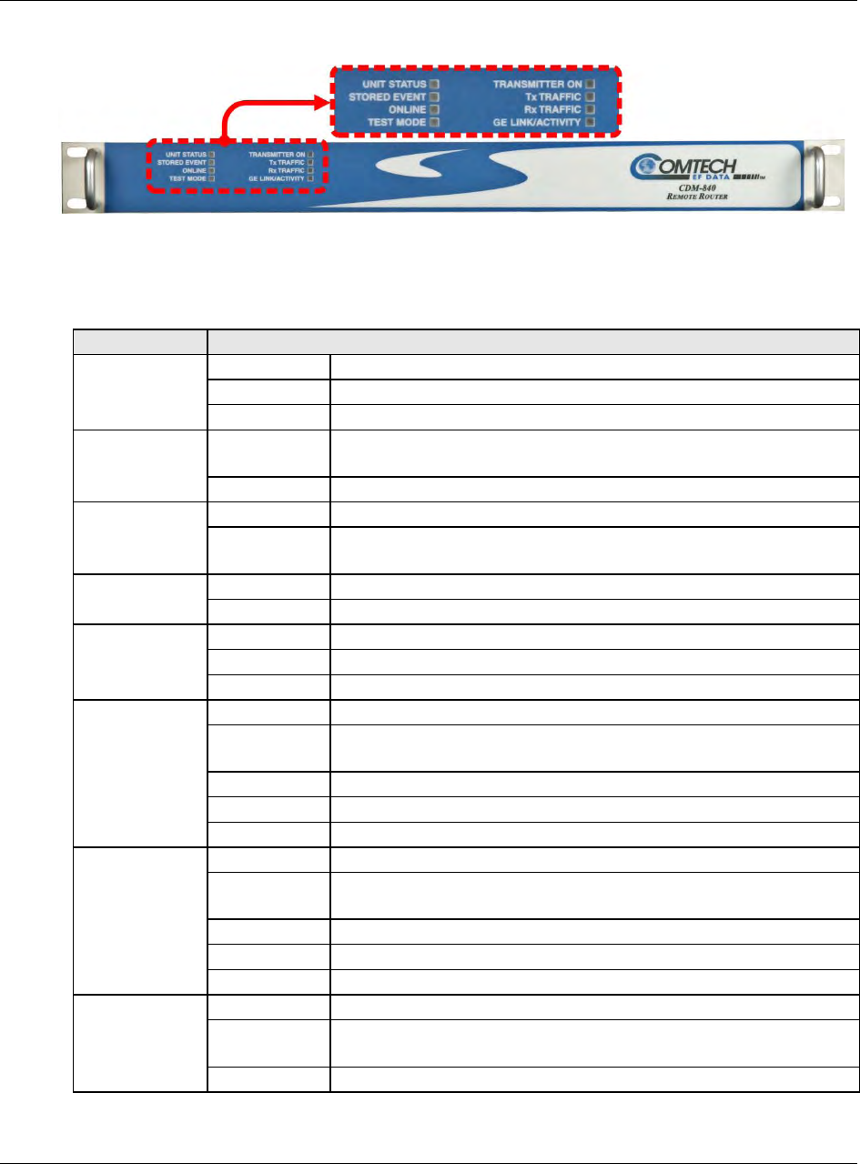
- 1.3.3.1 Front Panel 29
- 1.3.3.2 Rear Panel 30
- 1.4 CDM-840 Specifications 32
- 1.4.2 Bit Error Rate (BER) 33
- 1.4.3 Standard Assemblies 34
- 1.4.4 Optional Assemblies 34
- 1.4.5 Regulatory Compliance 34
- Chapter 2. INSTALLATION 35
- Installation MN-CDM840 36
- Chapter 3. REAR PANEL 41
- CONNECTIONS 41
- 3.1.1.1 Type ‘BNC’ 42
- 3.1.1.2 Type ‘TNC’ 42
- 3.1.1.3 Type ‘N’ 42
- 3.1.1.4 Type ‘F’ 43
- Chapter 4. UPDATING FIRMWARE 55
- • Local Echo = ON 56
- Updating Firmware MN-CDM840 57
- Chapter 5. FAST ACTIVATION 65
- PROCEDURE 65
- 5.2.1 FAST Configuration 67
- 5.2.2 FAST Upgrade 68
- Chapter 6. ETHERNET-BASED 69
- REMOTE PRODUCT 69
- 6.3 SNMP Interface 71
- 6.4.1 User Login 72
- 6.4.2.1 Virtual Front Panel 73
- 6.4.2.2 Navigation 75
- 6.4.2.3 Page Sections 75
- 6.4.2.4 Action Buttons 75
- 6.4.2.5 Drop-down Lists 76
- 6.4.2.6 Text or Data Entry 76
- 6.4.4.1 Home Pages 78
- 6.4.4.1.1 Home 78
- 6.4.4.1.2 Home 79
- 6.4.4.2.1 Admin 79
- 6.4.4.3 Admin 80
- 6.4.4.3.1 Admin 81
- 6.4.4.4 Admin 82
- Auto Logout Configuration 83
- 6.4.4.4.2 Admin 84
- 6.4.4.5 Configuration Pages 86
- FE – Management Interface 87
- VLAN Configuration 88
- E1 Configuration 90
- RAN Optimization 91
- E1 Port 91
- Time Slot Configuration 92
- Demodulator 94
- Demodulator Frequency 97
- Modulation) 98
- Rx ACM Configuration 99
- Rx ACM Status (read-only) 99
- Modulator Frequency 103
- Tx ACM Configuration 104
- Tx ACM Status (read-only) 105
- Tx ACM Events (read-only) 105
- (TOP) QoS Control Mode = OFF 106
- 6.4.4.5.2.3) 107
- QoS Rules Table (Edit) 109
- Receive WAN Labels 112
- Refresh Rates 113
- BUC Control 114
- BUC Status 115
- LNB Control 115
- LNB Status 116
- Add New Route 118
- Delete Route 118
- Route Table (Edit) 118
- IGMP Configuration 119
- IGMP Table 120
- DHCP Relay 121
- Add Static ARP 122
- Delete Static ARP 122
- Flush Dynamic ARPs 122
- ARP Table (Edit) 123
- Working Mode 123
- DNS Caching 124
- DNS Cache Flush 124
- ECM Remote Configuration 126
- Load Switching Configuration 128
- ToS Switching Configuration 129
- (ToS Rules Table) 129
- 6.4.4.6 Status Pages 130
- Ethernet Statistics 131
- Mod Statistics 131
- Demod Statistics 131
- Clear Statistics 132
- Clear Compression Counters 133
- Clear QoS Counters 135
- QoS Statistics 135
- E1 Transmit Statistics 137
- Clear E1 Receive Statistics 138
- E1 Receive Packet Statistics 138
- E1 Receive Statistics 139
- Traffic Throughput (kbps) 141
- RAN Link Quality 141
- RANOp Savings 141
- 6.4.4.6.2 Status 142
- 6.4.4.7 Utility Pages 143
- 6.4.4.7.1 Utility 143
- Save/Load Configuration 144
- BERT Config 145
- BERT Monitor 145
- Redundancy 145
- Console Configuration 145
- 6.4.4.7.2 Utility 146
- MANAGEMENT 147
- 7.2.1 Basic Protocol 149
- 7.2.2 Packet Structure 150
- 7.2.2.1 Start of Packet 150
- 7.2.2.2 Target Address 151
- 7.2.2.3 Address Delimiter 151
- 7.2.2.4 Instruction Code 151
- 7.2.2.7 End of Packet 153
- 7.3.1 Table Indexes 154
- Appendix A. REFERENCE 175
- DOCUMENTATION 175
- Appendix A MN-CDM840 176
- (ACM/VCM) 177
- A.4 E1 WAN/RAN Optimization 178
- Appendix B. FEC (FORWARD 181
- ERROR CORRECTION) OPTIONS 181
- B.2.1 Range of Data Rates 182
- B.3 VersaFEC 183
- (Short-block LDPC) 183
- B.3.1 Range of Data Rates 184
- Appendix B MN-CDM840 185
- Comtech VersaFEC® Codec 189
- Rate 0.488 BPSK 189
- Rate 0.533, 0.631, 0.706 190
- Rate 0.642, 0.711, 0.780 191
- Rate 0.731, 0.780, 0.829 192
- Appendix C. BRIDGE POINT-TO 193
- MULTIPOINT (BPM) OPERATION 193
- C.2.1 F lat Network 194
- C.2.3 VLAN Trunking 195
- C.3 Packet Processing 195
- C.3.2 Management Network 196
- C.4 IEEE 802.1Q Support 197
- C.4.1 VLAN Trunking 197
- C.4.2 Acces s Mode Support 197
- C.5 Multicast BPM Behavior 198
- Appendix C MN-CDM840 199
- C.9 Summary 205
- C.10 Glossary 206
- Appendix D. HEADER AND 207
- PAYLOAD COMPRESSION 207
- HTML 4.4:1 3.4:1 2.65:1 208
- Appendix D MN-CDM840 209
- Appendix E. DATA COLLECTION 213
- Appendix E MN-CDM840 214
- Appendix F. ENTRY CHANNEL 221
- MODE (ECM) 221
- Appendix F MN-CDM840 222
- F.2.3.1 Tap Message 227
- F.2.3.2 HCC Configuration 227
- F.2.3.3 Hub Operation 227
- F.4 Glossary of Terms 232
- Appendix G. WAN/RAN 233
- OPTIMIZATION 233
- G.1.2 RAN Inefficiency 234
- G.2 E1 RAN Optimization 235
- G.2.1 Process Overview 236
- Appendix G MN-CDM840 237
- G.2.3 Performance Monitoring 239
- G.2.3.2 RAN Link Quality 240
- G.2.3.3 RANOp Savings 241
- 480 • 333 • 2200 PHONE 244
- • 333 • 2161 FAX 244
Related products and manuals for Networking Comtech EF Data CDM-840
 (258 pages)
(260 pages)
(258 pages)
(260 pages)
© 2020, manymanuals.com. All rights reserved. | 0.023 s |
 Manymanuals.com
 Manymanuals.de
 Manymanuals.fr
 Manymanuals.it
 Manymanuals.pl
 Manymanuals.cz
 Manymanuals.es
 Manymanuals-pt.com
Comments to this Manuals