Comtech EF Data CDM-710G Specifications Page 67
- Page / 246
- Table of contents
- BOOKMARKS
- High-Speed Satellite Modem 1
- Errata A 3
- CDM-710G 7
- Table of Contents 9
- Figures 17
- PREFACE 19
- Electrical Safety 20
- Environmental 20
- Installation 20
- International Symbols 21
- CE Mark 21
- RoHS Compliancy 21
- Warranty Policy 23
- Limitations of Warranty 23
- Exclusive Remedies 24
- Customer Support 25
- Online Customer Support 25
- Preface MN-CDM710G 26
- Chapter 1. INTRODUCTION 27
- 1.1.2 Applications 28
- 1.2 Functional Description 29
- Introduction MN-CDM710G 30
- 1.3 Features 31
- 1.3.1 Physical Description 31
- 1.3.2 Major Assemblies 31
- 1.3.3 Dimensional Envelope 32
- 1.3.4 Physical Features 33
- 1.3.4.1 Front Panel 33
- 1.3.4.2 Rear Panel 34
- 1.3.6 Verification 35
- FAST System Theory 36
- FAST Implementation 36
- FAST Accessible Options 36
- 1.4 New in this Manual 37
- Figure 1-6. Spectral Mask 39
- 1.5.2 Modulator 41
- 1.5.3 Demodulator 42
- Maximum Level 43
- Minimum Level 43
- 1.5.4 Test Functions 45
- 1.5.5 Monitor Functions 45
- 1.5.6 Remote Port Operation 45
- 1.5.7 Data Rate Range 45
- Chapter 2. INSTALLATION 49
- 2.2 Mounting 50
- Installation MN-CDM710G 51
- Chapter 3. ETHERNET NETWORK 53
- CONFIGURATIONS 53
- MPORTANT 55
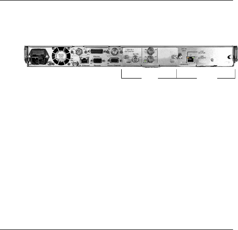
- Chapter 4. REAR PANEL 67
- CONNECTOR PINOUTS 67
- 4.2 IF Connections 68
- 4.2.1 J1 Tx IF Connectors 68
- 4.2.2 J3 Rx IF Connectors 68
- 4.4 Utility Connections 70
- Chapter 5. FLASH UPGRADING 73
- Flash Upgrading MN-CDM710G 74
- 5.4 USB Procedure 76
- Chapter 6. FRONT PANEL 77
- OPERATION 77
- 6.1.2 Front Panel Keypad 79
- 6.1.4 Menu Matrix 81
- 6.2 Opening Screen 82
- 6.3 SELECT: (Main) Menu 82
- 6.3.1 (SELECT:) Config 83
- 6.3.1.2 CONFIG: Tx 87
- (CONFIG:) Tx Æ FEC 87
- (CONFIG:) Tx Æ Mod 87
- (CONFIG:) Tx Æ Code 89
- (CONFIG:) Tx Æ SymRate 89
- (CONFIG:) Tx Æ Frequency 92
- (CONFIG:) Tx Æ Pwr 92
- (CONFIG:) Tx Æ Scram 93
- 6.3.1.3 CONFIG: Rx 93
- (CONFIG:) Rx Æ FEC 93
- (CONFIG:) Rx Æ Dem (Demod) 94
- (CONFIG:) Rx Æ Code 95
- (CONFIG:) Rx Æ SymRate 96
- (CONFIG:) Rx Æ Freq 96
- (CONFIG:) Rx Æ Eb/No 97
- (CONFIG:) Rx Æ PLL 97
- ENTER when done 102
- ENTER. Note the following: 102
- (CONFIG:) Intfc1 HSSI Æ Tx 103
- (CONFIG:) Intfc1 HSSI Æ Rx 104
- IMPORTANT 106
- ENTER. The 108
- ENTER 110
- 6.3.1.7 CONFIG: Ref 111
- 6.3.1.8 CONFIG: Aux 112
- 6.3.1.9 CONFIG: Alarms 113
- (CONFIG:) Alarm Mask: Æ Tx 113
- (CONFIG:) Alarm Mask: Æ Rx 113
- ◄ ► arrow keys, then 115
- ◄ ► arrow keys 115
- 6.3.2 SELECT: Monitor 116
- Demodulator Faults / Alarms 119
- 6.3.3 SELECT: Test 120
- (Available Some Interfaces) 121
- 6.3.4 SELECT: INFO 122
- 6.3.4.2 (SELECT:) INFO Æ Tx 122
- 6.3.4.3 (SELECT:) INFO Æ Rx 123
- 6.3.5 SELECT: Save/Load 123
- 6.3.6.3 (SELECT:) UTIL Æ ID 126
- (UTIL:) FAST Æ View 129
- Chapter 7. WEB SERVER 131
- INTERFACE 131
- 7.2 User Login 132
- 7.2.1 Web Server Menu Tree 133
- 7.3.1 Home Page 134
- 7.3.1.1 Home 134
- 7.3.1.2 Home 135
- 7.3.1.3 Home 136
- 7.3.2 Admin Pages 137
- 7.3.2.1 Admin 137
- 7.3.2.2 Admin 139
- 7.3.3.2 Config Mdm 142
- Chapter 8. SNMP INTERFACE 147
- 8.3 SNMP Community Strings 148
- 8.4 SNMP Traps 148
- 8.5 Common Private MIB 149
- SNMP Interface MN-CDM710G 150
- Chapter 9. TELNET INTERFACE 151
- Telnet Interface MN-CDM710G 152
- 9.3 Using Telnet 154
- 9.3.1 Telnet Examples 154
- Chapter 10. CLOCK MODES 155
- Clock Modes MN-CDM710G 156
- 10.3 CDI-60 HSSI Interface 158
- Chapter 11. FORWARD ERROR 161
- CORRECTION OPTIONS 161
- 11.2.1 Range of Data Rates 162
- Chapter 12. SINGLE G.703 171
- 12.2 Physical Description 172
- Chapter 13. HSSI INTERFACE 175
- (CDI-60) 175
- 13.2 Physical Description 176
- 13.3 Connector Pinout 177
- Continuous Clock 178
- Gap Clock 178
- GIGABIT ETHERNET (GigE) 181
- INTERFACE (CDI-70) 181
- Gigabit Ethernet Card 182
- 14.4 Specifications 184
- 1. Download the Files 186
- Appendix A. REMOTE CONTROL 191
- A.3 RS-232 192
- A.4 Basic Protocol 192
- A.5 Packet Structure 192
- A.5.5 Message Arguments 194
- A.5.6 End Of Packet 194
- A.6.1 Modulator 196
- A.6.2 Demodulator 205
- N/A 5 bytes Query only 214
- A.6.3 Modem 217
- A.6.4 Priority System 223
- A.6.5.1 MGC Format 234
- Appendix B. Eb/No 237
- MEASUREMENT 237
- Eb/No = 10 log 238
- -1) – 10 log 238
- (Spectral Efficiency) 238
- Appendix C. FAST ACTIVATION 241
- PROCEDURE 241
- C.2 Activation Procedure 242
- Units of Weight 245
- METRIC CONVERSIONS 245
- Units of Length 245
- Temperature Conversions 245
- 480 • 333 • 2200 PHONE 246
- • 333 • 2161 FAX 246
Related products and manuals for Networking Comtech EF Data CDM-710G
 (258 pages)
© 2020, manymanuals.com. All rights reserved. | 0.041 s |
 Manymanuals.com
 Manymanuals.de
 Manymanuals.fr
 Manymanuals.it
 Manymanuals.pl
 Manymanuals.cz
 Manymanuals.es
 Manymanuals-pt.com
Comments to this Manuals