Comtech EF Data UT-4518E Specifications Page 54
- Page / 132
- Table of contents
- TROUBLESHOOTING
- BOOKMARKS
- UT-4500-A Series 1
- Errata A 3
- TABLE OF CONTENTS 7
- FIGURES 14
- PREFACE 15
- Preface MN-UT4500A 16
- Warranty Policy 18
- Limitations of Warranty 18
- Exclusive Remedies 19
- Customer Support 20
- Online Customer Support 20
- Chapter 1. INTRODUCTION 21
- 1.2 Features 22
- 1.2.2 Dimensional Envelope 23
- 1.2.3 Front Panel 24
- 1.2.4 Rear Panel 24
- 1.3 Theory of Operation 25
- 1.3.1 Applications 25
- 1.3.2 RF Signal Conversion 26
- 1.3.3 Monitor & Control 27
- Introduction MN-UT4500A 28
- Chapter 2. INSTALLATION 39
- 2.2 Installation 40
- Installation MN-UT4500A 41
- 2.4 Connect External Cables 43
- Chapter 3. REAR PANEL 45
- CONNECTORS 45
- IMPORTANT 46
- IMPORTAN 47
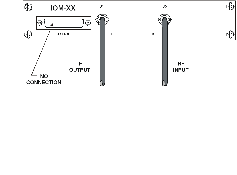
- 3.3 Cable Connections 53
- Module (TSM-XX) Installed 55
- Chapter 4. FLASH UPGRADING 57
- Flash Upgrading MN-UT4500A 58
- Chapter 5. FRONT PANEL 63
- OPERATION 63
- 5.1.2 LED Indicators 64
- 5.1.3 Keypad 65
- 5.2 Opening Screen 66
- 5.3 Main Menu 66
- 5.3.1.1 CONFIG: OUTPUT 67
- 5.3.1.3 CONFIG: REDUNDANCY 71
- 5.3.1.5 CONFIG: COLDSTART 73
- 5.3.2 MONITOR 74
- 5.3.3 FAULTS 74
- 5.3.3.1 FAULTS: CURRENT 74
- 5.3.4 PRE-SELECTS 75
- 5.3.4.1 PRE-SELECTS: LOAD 76
- 5.3.4.3 PRE-SELECTS: CLEAR 76
- 5.3.5 UTILITY 77
- 5.3.5.5 UTILITY: SLOPE 78
- 5.3.5.6 UTILITY: LAMP-TEST 79
- 5.3.5.7 UTILITY: FIRMWARE 79
- MANAGEMENT 81
- Chapter 6. ETHERNET 81
- 6.3.3 SNMP Traps 83
- 6.4 Telnet Interface 84
- Appendix A. REMOTE CONTROL 87
- A.2.2 TIA/EIA-232 (RS-232) 88
- A.2.3 Ethernet (100BASE-TX) 88
- A.3 Access Methods 88
- A.3.1 Direct Access 88
- A.3.2 Indirect Access 89
- A.4 Addresses 89
- A.4.1 Physical Address 89
- A.4.2 Virtual Address 89
- A.6 Message Structure 91
- A.6.1 Start Character 91
- A.6.2 Device Address 91
- A.6.3 Command 91
- A.6.4 Confirmation Response 92
- A.6.5 Error Response 92
- A.6.6 End of Message 92
- A.6.6.1 Command Ending 92
- A.6.6.2 Response Ending 92
- A.7.1 Utility Commands 93
- A.7.1.1 Time 93
- A.7.1.2 Date 93
- A.7.1.5 IP Address 94
- A.7.1.6 IP Gateway 94
- A.7.1.7 Physical Address 95
- A.7.1.8 Baud Rate 95
- A.7.1.9 LCD Contrast 95
- A.7.1.10 LCD Brightness 95
- A.7.1.11 Screen Saver Mode 96
- A.7.1.13 VFD Brightness 96
- A.7.1.16 Equipment Type 97
- A.7.1.17 Part Number 97
- A.7.1.20 Firmware Image 98
- A.7.1.22 Force Reboot 99
- A.7.2.1 Frequency 99
- A.7.2.2 Attenuator 99
- A.7.2.3 Cold Start 100
- A.7.2.4 Mute 100
- A.7.2.5 Carrier Mute Mode 100
- A.7.2.6 Redundant Mute Mode 100
- A.7.2.7 Auto Fault Recovery 101
- A.7.2.8 Program Preset 101
- A.7.2.9 Display All Presets 101
- A.7.3.1 Redundant Mode 102
- A.7.3 Modes 102
- A.7.3.3 Backup Mode 103
- A.7.4 Status Commands 104
- A.7.4.2 Maintenance Status 104
- A.7.4.3 Utility Status 105
- A.7.4.4 Alarm Status 105
- Command Details 106
- Appendix A MN-UT4500A 107
- A.7.5 Stored Alarms 108
- A.7.5.1 Total Stored Alarms 108
- A.7.5.3 List All Alarms 108
- A.7.6 Error Processing 109
- A.7.6.1 General Errors 109
- A.7.6.3 Mode Errors 109
- A.7.6.4 Time-Outs 109
- A.7.7 Command Summaries 110
- Appendix B. REDUNDANT 113
- SYSTEM OPERATION 113
- B.2.2 Detachable Modules 114
- Installed 115
- TSEQM-XX Installed 116
- TSM-XX Installed 117
- Appendix B MN-UT4500A 118
- B.4.1 Initial Configuration 120
- adjusted to minimize 125
- Appendix C. MAINTENANCE AND 127
- TROUBLESHOOTING 127
- Appendix C MN-UT4500A 128
- C.2.3.3 RF Converter Module 129
- C.2.3.7 Temperature Fault 129
- C.2.4 Converter I/O Modules 130
- C.3 Spares 130
- METRIC CONVERSIONS 131
- Units of Length 131
- Temperature Conversions 131
- Units of Weight 131
- 480 • 333 • 2200 PHONE 132
- • 333 • 2161 FAX 132
Related products and manuals for Unknown Comtech EF Data UT-4518E
 (184 pages)
(182 pages)
(162 pages)
(184 pages)
(182 pages)
(162 pages)
© 2020, manymanuals.com. All rights reserved. | 0.031 s |
 Manymanuals.com
 Manymanuals.de
 Manymanuals.fr
 Manymanuals.it
 Manymanuals.pl
 Manymanuals.cz
 Manymanuals.es
 Manymanuals-pt.com
Comments to this Manuals